Oliver Cardwell/Project
Contents |
Project
This page is under construction ...
Introduction
What is my project all about? Well for my honours project I am looking at the performance of iterative inverse kinematic algorithms. Yes there are a few big words in that title so I will break it down and you will see that its not so bad.
My project focuses on the inverse kinematics of simple joint chains such as a robotic arm or the leg of an computer animated character. If we want to position the end of the robotic arm (end-effector) then we need to tell each joint in the arm to move to a particular angle. Once the robot arm has moved each of its joints to the required position the end-effector will (hopefully) be in the desired position. The hard part of this and coincidently that 'inverse' part of the title is finding out what angles you need at each joint so that the end-effector ends up at the correct location. Enter the CCD algorithm ...
The Cyclic Coordinate Descent (CCD) algorithm is an iterative algorithm that operates on a joint chain and works by converging the end-effector to the desired target location. The CCD algorithm is relativity simple to implement and this makes it very popular for use in the fields of robotics and computer animation and computer games.
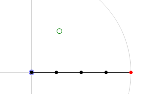
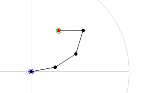
Below are to images that will help clarify what the CCD algorithm achieves. The first image is the 'before' shot. The joint chain is stretched out straight with the base of the joint chain at the origin. The green circle is the target location and the red circle is the end-effector of the joint chain. The second image is the 'after' shot. In this second image we can see the result of running the CCD algorithm on the joint chain. You will note that the end-effector has moved to the target location. This is a pretty good indication that everything has gone smoothly in the algorithm, it has been able to find the rotation required for each joint in order hit the target.
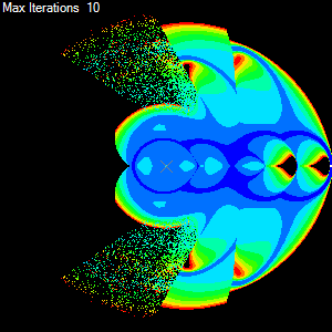
Ok so for each target we have a bunch of information regarding the behaviour of the CCD algorithm, these include the number of iterations done to get the end-effector to the target and others such as the total amount of rotation taken by all the joints. If we now use this information to colour the target and we make as many targets as there are pixels then we get a colourised map of performance of the algorithm with the joint chain. The result can be seen below.
Requirements
The program needs to able to render a metric map for a given size joint chain and a given iterative IK algorithm.
Input:
- Number of joints in the chain.
- Type of iterative IK algorithm (will be using at least two initially)
- Behaviour parameters for the algorithm, including:
- Maximum number of iterations to attempt
- Tolerance distance required for the end-effector to be considered at the target
- Size of the metric map (image dimentions size x size)
- Metric to display on the metric map
Output:
- Metric map (size x size) image
- Range of results for the rendered metric map
Initial Design
The initial design breaks the whole problem in smaller achievable problems. Each sub problem can be outline in a basic flow such as:
- Create the required number of joints
- Create a 2D buffer to hold the results, one element for each pixel/target
- For each target in the buffer:
- Reset the joint chain to its default position
- Run the algorithm over the joint chain for this target
- Save the result to the buffer
- Loop over the buffer and find the min and max (range) for the required metric
- Create an image the same size as the buffer
- For each element in the buffer:
- Use the resulting metric range to colourise the result
- Store the colour in the corresponding image pixel
Note: Should mention using multi threading
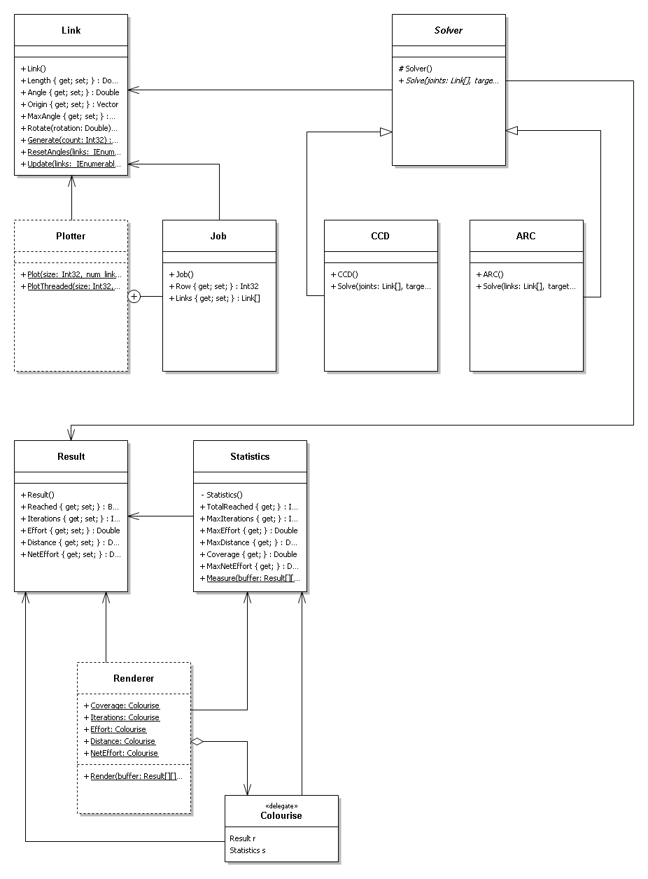
First I identified what was going to be changing and the obvious answer is the joint chain. So I designed a Link (joint) class. This class would represent a single link with a static length and dynamic angle. Also included was a origin field that would be the 2D location of the base or origin of the joint.
In order to represent a joint chain I would simply use an array of links. This way it naturally enforced an order and length, so therefore would work perfectly as a joint chain.
Next I needed a Solver that would take a joint chain and modify the angles of the joints until the end-effector was at a given target location. Knowing that I wanted to be able to test different algorithms, I made this class abstract and then implemented a concrete CCD class from it.
Now that I had the ability to represent and solve a IK problem on a simple joint chain I needed a way to record what happened to the joint chain during the solve routine. So I created a Result class that kept the results of various metrics and made is the return value for the Solver.Solve() method. By doing this I let the implementation of the Solver take care about filling in the various metric values.
So far I think that I was off to a good start. I had simple classes to represent joint, solver and result. Now I need to take these and apply them to each pixel in an image and render the result using colours. Firstly I decided that I need to collect all the data. So next up I designed a Plotter class. This class would have the responsibility of creating a 2D array of results, each result representing a point in a square grid that would then be mapped onto a pixel in a square image (metric map). The plotter class turned out to only have a single method and did not need to contain any state between calls so this class was defined as a static class with a single static method. Through this method you could pass all the required information the plotter needed to produce a 2D array of results. I thought this was a nice solution as it kept all the behaviour of the solver in a single call and would allow me to break the problem up further into chunks that I could process simultaneously over multiple threads. So that's exactly what I did.
UML Diagram


