Oliver Cardwell/Project
(→Final Design) |
(→Final Design) |
||
| Line 212: | Line 212: | ||
; DistanceMetricMap Class | ; DistanceMetricMap Class | ||
: Again we inherit from the '''RangedMetricMap<T>''' class, this time with type of ''double''. This class shows the distance travelled by the end-effector to reach each target point. | : Again we inherit from the '''RangedMetricMap<T>''' class, this time with type of ''double''. This class shows the distance travelled by the end-effector to reach each target point. | ||
| + | |||
| + | |||
| + | == Discussion == | ||
= Comments = | = Comments = | ||
Revision as of 22:26, 30 September 2010
Contents |
Introduction
What is my project all about? Well for my honours project I am looking at the performance of iterative inverse kinematic algorithms. Yes there are a few big words in that title so I will break it down and you will see that its not so bad.
My project focuses on the inverse kinematics of simple joint chains such as a robotic arm or the leg of an computer animated character. If we want to position the end of the robotic arm (end-effector) then we need to tell each joint in the arm to move to a particular angle. Once the robot arm has moved each of its joints to the required position the end-effector will (hopefully) be in the desired position. The hard part of this and coincidently that 'inverse' part of the title is finding out what angles you need at each joint so that the end-effector ends up at the correct location. Enter the CCD algorithm ...
The Cyclic Coordinate Descent (CCD) algorithm is an iterative algorithm that operates on a joint chain and works by converging the end-effector to the desired target location. The CCD algorithm is relativity simple to implement and this makes it very popular for use in the fields of robotics and computer animation and computer games.
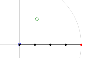
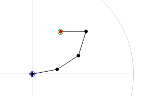
Below are two images that will help clarify what the CCD algorithm achieves. The first image is the 'before' shot. The joint chain is stretched out straight with the base of the joint chain at the origin. The green circle is the target location and the red circle is the end-effector of the joint chain. The second image is the 'after' shot. In this second image we can see the result of running the CCD algorithm on the joint chain. You will note that the end-effector has moved to the target location. This is a pretty good indication that everything has gone smoothly in the algorithm, it has been able to find the rotation required for each joint in order hit the target.
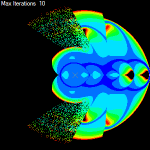
Ok so for each target we have a bunch of information regarding the behaviour of the CCD algorithm, these include the number of iterations done to get the end-effector to the target and others such as the total amount of rotation taken by all the joints. If we now use this information to colour the target and we make as many targets as there are pixels then we get a colourised map of performance of the algorithm with the joint chain. The result can be seen below.
Cool eh. Now we can easily see how the CCD algorithm performs using a given set of parameters. We can see that it has trouble reaching around behind itself and we can clearly see the regions of the joint chains workspace that it can reach easily due the simple colouring. Ok now to get onto designing a nice simple object-oriented solution that will make generating various metric maps a snap. But first we need to look at some basic requirements.
Requirements
The program needs to able to render a metric map for a given size joint chain and a given iterative IK algorithm.
- Input
- Number of joints in the chain.
- Type of iterative IK algorithm (will be using at least two types initially but we want to be able to add more easily)
- Behaviour parameters for the algorithm, including:
- Maximum number of iterations to attempt
- Tolerance distance required for the end-effector to be considered at the target
- Size of the metric map (image dimensions size x size)
- Metric to display on the metric map
- Output
- Metric map (size x size) image
- Range of results for the rendered metric map
In order to render a metric map we follow the following general algorithm.
- Algorithm
- Create the required number of joints
- Create a 2D buffer to hold the results, one element for each pixel/target
- For each target in the buffer: (see note *)
- Reset the joint chain to its default position
- Run the algorithm over the joint chain for this target
- Save the result to the buffer
- Loop over the buffer and find the min and max (range) for the required metric
- Create an image the same size as the buffer
- For each element in the buffer:
- Use the resulting metric range to colourise the result
- Store the colour in the corresponding image pixel
* note: This loop can be very computationally expensive, especially with large images and high thresholds. So this loop is targeted for sub division to allow parallel execution.
Internally it does not really matter the structure or the representations as long as the CCD (or any alternative) algorithm works correctly and has access to the joint angles. In saying that lets check out the initial design.
Initial Design
The initial design follows closely to this simple step by step, procedural, approach to the problem of rendering a metric map. The steps are outlined as follows:
Description
First lets take a closer look at areas in the problem domain. These areas are not analogous to classes, but as we shall see, they are a close to the initial design.
- Structure
- First I identified what was going to be changing and the obvious answer is the joint chain. So I designed a Link (joint) class. This class would represent a single link with a static length and dynamic angle. Also included was a origin field that would be the 2D location of the base or origin of the joint.
- In order to represent a joint chain I would simply use an array of links. This way it naturally enforced an order and length, so therefore would work perfectly as a joint chain.
- Algorithm
- Next I needed a Solver that would take a joint chain and modify the angles of the joints until the end-effector was at a given target location. Knowing that I wanted to be able to test different algorithms, I made this class abstract and then implemented a concrete CCD class from it.
- Now that I had the ability to represent and solve a IK problem on a simple joint chain I needed a way to record what happened to the joint chain during the solve routine. So I created a Result class that kept the results of various metrics and made is the return value for the Solver.Solve() method. By doing this I let the implementation of the Solver take care about filling in the various metric values.
- Plot
- So far I think that I was off to a good start. I had simple classes to represent joint, solver and result. Now I need to take these and apply them to each pixel in an image and render the result using colours. Firstly I decided that I need to collect all the data. So next up I designed a Plotter class. This class would have the responsibility of creating a 2D array of results, each result representing a point in a square grid that would then be mapped onto a pixel in a square image (metric map). The plotter class turned out to only have a single method and did not need to contain any state between calls so this class was defined as a static class with a single static method. Through this method you could pass all the required information the plotter needed to produce a 2D array of results. I thought this was a nice solution as it kept all the behaviour of the solver in a single call and would allow me to break the problem up further into chunks that I could process simultaneously over multiple threads. So that's exactly what I did. (Note: PlotThreaded() and the internal Job class).
- Summarise
- Great now we only need to loop over all the results in the results buffer (2D array) and compute a colour value for each result, saving the computed colour to a cosponsoring image pixel. But how do I know what metric we want to show and what is the range of that metric in our result buffer? An into the fray I designed the Statistics class. This class would simply loop through the results buffer and compile a series of ranges for each metric in the result class. In this case I decided that I did not want it doing all that work in the constructor so I made the default constructor private and instead created a static method that when called would create and return the class with all the field filled in. In this way only the static method creates the and has write access to the classes field. What's returned is effectively a 'read-only' class.
- Render
- For the final step I needed a way to colourise each result. Because the bulk of this operation would be the same no matter what metric we wanted to measure I decided to design a Renderer class. This would do all the grunt work of looping over results and then I would use a simple delegate method Colourise, passed to the renderer, do the simple job of selecting the appropriate metric and using the metrics range define a colour value.
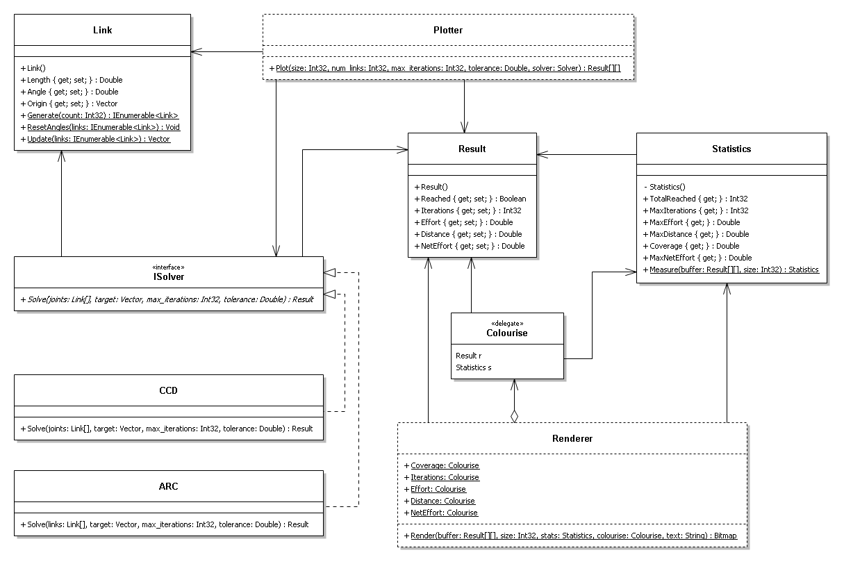
UML Diagram
Class Descriptions
- Link Class
- The Link class is farily straigt forward. It simply represents a structure with a length and angle value. It also contains an origin vector that represents the location of the base of the link in the chain.
- ISolver Interface
- The abstract solver class is a template for a solve behaviour, or solve algorithm. The solver class outlines a single Solve() method that takes a number of parameters including a list of links and returns a result.
- CCD Class
- The CCD class implements from the Isolver interface, and implements the CCD algorithm through the Solve() method.
- ARC Class
- Like the CCD class, the ARC class implements from the Isolver interface, and implements an experimental IK algorithm through the Solve() method.
- Result Class
- The result class is a simple data class. It contains the resulting metrics from a call to a Solve() method from the abstract solver class.
- Plotter Class (static)
- The static plotter class has only a single method, Plot() and no state. This single method take a number of parameters for generating a result for each point on a square grid and does just that. The Plot() method returns a 2D array of results, one for each point on the square grid. This approach therefore computes all possible metrics in a single pass.
- Statistics Class
- The statistics class is a simple read-only summary of results class. The class is given a list of results through its static method Measure(), and produces a summary of all the results. These include finding the maximum values and tallies.
- Colourise (delegate)
- The colourise delegate, simply templates a method that takes a result and the summary of results and returns an appropriate colour for a certain metric. Therefore in order to produce different metric maps of different metrics, or colour scales, we simply have to write a method with the same signature and pass it to the Render() method on the static renderer class.
- Renderer Class (static)
- The static renderer class, like the static plotter class, has a single method and no state. The Render() method takes a number of parameters including a 2D array of results, one per pixel, and a colourise delegate (behaviour). It uses the colourise delegate to create a coloured image of the results.
Discussion
Ok now we have finished the initial design we can put on our OO hat and take a closer look.
The first thing we may notice is that there is not a lot of OO going on here. Sure we have used classes to implement a "separation of concerns" but a lot of those classes appear to have no state. Should this be a concern? What about the use of an abstract Solver class that does not have any implemented methods? What's with all the static methods in Link? And what's with the private constructor in the Statistics class? Well it seems that we have a few good questions to start with so we will now attempt to address them one at a time.
- Properties, getters and setters
- Starting with the humble Link class we can examine the use of getters and setters (properties in C#). Logically, for this project, we only want the angle of the joint to change not the length. And in saying this we may not want the link to just blindly rotate to a given angle as there may be constraints to the amount of rotation required. An attempt to fix this in the initial design looks to have been attempted with the inclusion of the Rotate() method that takes a requested change in angle and returns the actual change made. This is a good attempt as it hides the details of the link but by leaving all those public setters it does not go all the way. The Length, Angle and Origin are needed in processing a link but altering the state of the Link class should be limited to the Rotate() method only.
- Abstract class vs Interface
- The abstract Solver class defines only a single method and no state. This looks like it would be the perfect candidate to be an interface instead of an abstract class. In this situation (only abstract methods and no state) the only reason that we may want to keep this as an abstract class is if we only want our subclasses to inherit from a single class (itself).
- Static Factory Methods
- What's this you ask? It is best described as the most simple form of Factory Method, and allows defer the creation of an object to one of its static methods. Why would you want to do that when you have a perfectly good constructor that does effectively the same thing? There are a number of reasons why the use of a static factory method may be preferable over the usual constructor method. If creating your object is a not trivial task, as in it requires a bit of computing to create, and has the possibility of failure then using the a standard constructor ..... (diagram would clarify this)
Final Design
Given the initial design it is obvious that we need to give it a thorough OO makeover. So for starters lets look more closely at the problem domain and see if we cannot separate the current procedural based design into recognisable and useful objects.
The concept of a link has a strong relation to the real world, and great for encapsulating in OO so we will leave that class mostly intact. However the concept of a list of links is a chain. This chain object is a list of links but with its own properties and methods. For example we often need to reset(set) the angles of all the links in a list. A chain class would allow us to encapsulate these ideas into a useful class.
Building on this idea of a chain class we can add a move() method that moves the end-effector of the chain to a given target. This is a simple extension of the chain class, but does not leave much flexibility for implementing different move algorithms. So we will make the chain class abstract and leave any inheriting classes to implement the move behaviour. By solving this behaviour with inheritance we
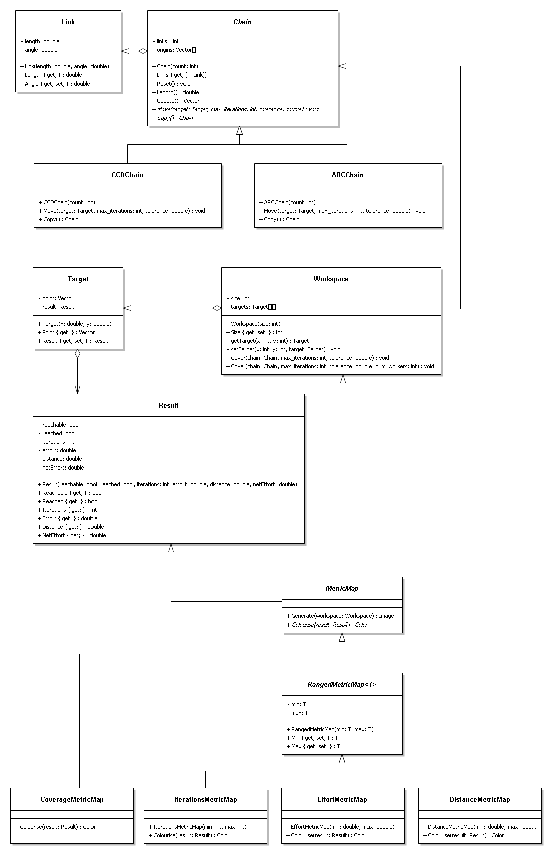
UML Diagram
Class Descriptions
- Link Class
- This falls straight out of the problem domain. It simply has a static length and a offset current angle.
- Chain Class (abstract)
- Again this comes straight out of the problem domain. A chain is simply a list of links. By looking at the chain as its own object we can use it as the basis for a couple of routines that we do on a chain, such as get the chain's length or reset the angle on each link in the chain. Most importantly though, we can allow an inheriting class implement the behaviour of the Move() method. This method is where the IK algorithm happens in the sub-class.
- CCDChain Class
- This is the infamous CCD algorithm. This class inherits from the abstract Chain class and implements the Move() method in accordance with CCD algorithm.
- ARCChain Class
- This is the ARC algorithm, an experimental IK algorithm. Like the CCDChain, this class inherits from the abstract Chain class and implements the ARC behaviour through Move() method.
- Result Class
- This class is a simple read-only data class. It is generated by the chain's Move() method. An object of type Chain must fill in all the parameters of the Result class through the Result class's constructor. Once the Result class is constructed, all the values are read-only. This is because we do not want the Result classes values to be tampered with by another object.
- Target Class
- This class represents the instructions and results of a chain moving it's end-effector to a target. The Target class groups together a target point (x,y), and the Result object. The target point is generated by the Workspace class and the Result class is generated by the Move() method in the Chain class.
- Workspace Class
- This is the workspace of a chain. Essentially it is a collection of Target objects that the chain will try and move to. Each of these targets corresponds to a pixel in the final metric map but for now they hold the the target point and the result of the chain's move, ready to be transformed into a coloured metric map. The Workspace class takes care of generating the results to all the targets from the given chain, through the Cover() method. To speed up this potentially expensive operation an optional third argument can be passed to the Cover() method that uses a thread-pool to share the computational load.
- MetricMap Class (abstract)
- This class is the base class for any type of metric map. It takes care of creating an image and loops over a workspace given to the Generate() method mapping a colour to each pixel through its abstract Colourise() method.
- RangedMetricMap<T> Class (abstract)
- This class extends a MetricMap class by allow you specify a type <T> and a range (min, max) that the metric will be compared to for colouring.
- CoverageMetricMap Class
- This simple class implements MetricMap class. Because it will only be displaying a colour if the target was reached we do not need to inherit from the RangedMetricMap<T> class. Instead we simply implement the Colourise() method to return black, if the target was not reached, and white if it was.
- IterationsMetricMap Class
- This time we inherit from the RangedMetricMap<T> and use a type of int. Therefore we can construct this metricmap with a min and max parameter and have the colour scaled between these values. This is an important property because it allows use to use the same range between different chain configurations and therefore get a better comparison between them.
- EffortMetricMap Class
- Again we inherit from the RangedMetricMap<T> class, this time with type of double. This class shows the amount of effort taken to reach each target point.
- DistanceMetricMap Class
- Again we inherit from the RangedMetricMap<T> class, this time with type of double. This class shows the distance travelled by the end-effector to reach each target point.
Discussion
Comments
Please leave any comments that you have regarding this project or even the writing of this wiki page in this comments section.
Made a few grammar changes and added links. LukeRobinson
- Thanks Mr Robinson, I see now that my UML diagram is missing almost all of its associations. Fixed now.
