Tanmay's Design Study
Tanmay Bhola (Talk | contribs) |
Tanmay Bhola (Talk | contribs) (→Maxims and Heuristics) |
||
| Line 68: | Line 68: | ||
*[[Tell, don't ask]] | *[[Tell, don't ask]] | ||
| − | Command pattern | + | |
| − | + | Command pattern | |
| + | Observer push config | ||
| + | |||
*[[Program to the interface not the implementation]] | *[[Program to the interface not the implementation]] | ||
*[[Favor composition over inheritance]] | *[[Favor composition over inheritance]] | ||
| − | In composite | + | |
| + | In composite | ||
| + | |||
*[[Open closed principle]] - | *[[Open closed principle]] - | ||
More components can be added at any time | More components can be added at any time | ||
| − | |||
== Discussion and Design Critique == | == Discussion and Design Critique == | ||
Revision as of 09:43, 30 September 2010
Contents |
Introduction
Welcome to the world of Digital Logic. Ever wondered what they teach at the College of Engineering that is different from the material taught at Department of Computer Science and Software Engineering ? Being a computer engineering student, I took this opportunity to perform Object-Oriented Analysis and Design of a 'Digital Logic Circuit Simulator'. Digital Circuits are constructed by joining simple logic elements and form the basis of our 'Embedded Systems' oriented programme. The system was designed and implemented specially for COSC427, and was not a part of another university project.
Background
Building complex digital structures like computers and microcontrollers without a simulation tool is similar to releasing a program without compiling/testing. Hence, designers always resort to simulation tools to check the correctness of their design before building the prototype. These circuits are essentially complex networks of simple logic components like logic gates, wires, clocks etc.
Logic Gates
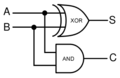
Half Adder Circuit
Full Adder Block Diagram
Full Adder Symbol


A digital logic simulator gives the user an ability to join simple logic elements in order to study the behaviour of complex digital circuits. My approach to this problem was to design an 'Event Driven Simulator' where events (change in state of something) trigger further events in the system at a later time. The main tasks revolved around the elementary components of the circuit and scheduling events that take place in the system. These can be further broken down into :
- 1) Wires --- These carry digital logic signals between components and have state associated with them.
- 2) Digital Function Blocks --- These perform functions to generate output signal(s) based on input signal changes. They need to listen for changes in the state of wires connected to the inputs of these blocks. An example of a function block is an and logic gate. It performs the bitwise AND function ( X = A.B) over inputs A and B.
- 3) Events --- The simulation is purely event based. This means that changes in the state of a wire can lead to generation of various events in the system. These contain a timestamp of execution along with the associated component.
My primary focus for this design study was on modelling the core classes of the simulator rather than its GUI implementation. The aim was to design a system that modelled the real world and could be extended in the future to incorporate GUIs and more components/ modelling techniques.
Requirements
- 1) Adding components : A User should be able to add new components to the system. These components can be a basic logic element or a combination of a series of elements. The user should also be able to copy simple elements in order to quickly build up a circuit. This is useful as many basic elements like logic gates are repeated in the circuit.
- 2) Connecting components with wires : A user should be able to assign connecting wires to the component input/ output ports. On connection, the component should be ready to respond to changes in the state of the wire.
- 3) Scheduling events: Timing is crucial in a digital logic simulation. This makes scheduling events an important task for this 'event driven' simulation software. Function blocks generate events with variable time delays (also known as propagation delays). These need to be executed by the system in the correct order, else the final output of the simulation would be incorrect.
- 3) Running the simulation and viewing results : Once the circuit has been wired up, a user should be able to run the simulation and view the results of the simulation. At this point, a basic text based output with timing information was sufficient. However, a GUI output (showing a graph) might be desired in the future.
UML Diagram Of Design

Design Detail
The focus was to make the design simple and extensible. Most of the classes map to the requirements discussed in the previous section. The design models the real world, as most of the classes were designed keeping in mind the circuits people work with, and the things they need to simulate.
- Component and Ports: The component represents a functional block in the circuit. Every component has at least one port to interact with the rest of the circuit. Ports could be input ports or output ports. Components could be in the form of simple logic gates (and/or/xor/nand) or a combination of these forming more complex components (like adders). To represent this part-whole heirarchy of components, the Composite pattern was used in the design. Logical circuits usually involve a huge number of the same components (like and/or gates). Prototype pattern was used To help the user quickly build up the circuit. This allows the user to create just one ComponentModule object and use the copy() method to generate multiple objects of the same kind.
- Wire : As described above, a wire is a container for a logic signal and links the output of one component to the input of another. As the signal propagates along the circuit, various events are generated to update the state of the wire after a certain delay interval. The user assigns a name to the wire on creation which can be used for generating the simulation results. The observer pattern was used to assist the wire in informing the connected ports about the change in its state. Input Ports add themselves as observers to the wire. This also allows us to model T-Junctions in the circuit (same wire going into multiple ports ) without having to add Junction type components each time. A wire class was designed instead of the
- Event: The Event class represents a discrete logic event that occurs in the simulation. A generic event has a time stamp and a task to execute at that time in the simulation. At the moment, events are created when a component changes the value of its output(s) based on the change in state of its input(s). The Event has a fire() method, which allows the system to execute it when required.
- Logic Level: This is a simple enumeration to model the IEEE Logic Levels. It offered a better abstraction to Logic High and Logic Low rather than using boolean variables for the representation. It would also allow addition of 'z' or high impedance signal level if required, without breaking the current design.
- Simulator: Performs the function of simulating the digital circuit by firing timely events. It contains a priority queue to which events are added and arranged based on the first one to be executed.
Design Patterns
Design patterns were used in this design to model the domain and solve challenging design problems. The design patterns used have been listed below, along with an explanation of how they were applied.
Observer
The model implements the observer pattern in two different areas in the design . It uses Observer pattern to model the relationship between wires (subjects) and components(observables). Change in the state of a wire demands re-computation of the outputs of attached ports, which triggers events in the system. The observer helps in automatically updating all the dependents in the one-to-many relationship modelled in the design. A port is added to the list of observers of the wire as soon as it is wired up. This helps us in modelling the real world, where on soldering a wire to a component, we expect it to change with changes to the state of the wire.
Another place the observer pattern was found to be applicable for the software and its future extensions was in the Simulator Class.
Command
Composite
Prototype
Singleton
Maxims and Heuristics
Command pattern Observer push config
In composite
More components can be added at any time
Discussion and Design Critique
1) The Composite Design Pattern: No-Op Overrides Vs Dependency Inversion Principle
2) Push Vs. Pull Configuration of the Observer
3) Single Responsibility Principle : Violated in Simulator.