Tanmay's Design Study
Contents |
Introduction
Welcome to the world of Digital Logic. Ever wondered what they teach at the College of Engineering that is different from the material taught at Department of Computer Science and Software Engineering ? Being a computer engineering student, I thought I would take this opportunity to perform Object-Oriented Analysis and Design of a 'Digital Logic Circuit Simulator'.Digital Circuits, that are constructed by joining simple logic elements, form the basis of our 'Embedded Systems' oriented programme.
Outline
A digital logic simulator gives the user the ability to join simple logic elements to study the behaviour of complex digital circuits. My approach to this problem would be designing an 'Event Driven Simulator' where events (change in state of something) triggers further events in the system that happen at a later time. This model of this simulator will revolve around the elementary components from which the circuit is constructed as well as the time-events taking place in the system. These can be further broken down into :
- 1) Wires --- Carry binary logic signals between components
- 2) Digital Function Blocks --- These perform some special function to generate output signal(s) based on some inputs. They need to listen for changes in the state of wires connecting these blocks.
- 3) Events --- to help model the time delay of performing various tasks during the simulation. A change in the state of 1 wire might trickle down to changes in the neighboring wires based on the output of the connecting function blocks.
My primary focus for this design study would remain on the core classes of the simulator rather than its GUI implementation.
Background
Logic Gates
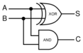
Half Adder Circuit
Full Adder Block Diagram
Full Adder Symbol


User Stories
Requirements
- 1) Adding Components : A User should be able to add new components to the system. These components can be a basic logic element or a combination of a series of elements.
- 2) Connecting Components with Wires : A user should be able to assign connecting wires to the component inputs/ outputs.
- 3) Running the Simulation : Once the circuit has been wired up, a user should be able to run the simulation and view the results via a component like a probe.
Constraints
First Attempt
Modelling Components using the Composite Pattern
Components could be in the form of simple logic gates (and/or/xor etc.) or a combination of these forming more complex components. The first pattern that comes to mind when thinking about part-whole hierarchies is the Composite Pattern. Hence, this pattern will be used for modelling the components as a start. A high level interface would be used to hide the complexity of individual components and encourage programming to the interface, not the implementation.
Lower level components should be able to take in Wires as their inputs and outputs to help with wiring up the circuit.
Modelling a Wire
A wire is essentially a link between two components, and carries (holds) a '1/0' value at any time. The outputs of components SET the value of the view while this change in the value triggers events in components via their inputs. The Observer pattern might be helpful in notifying a subset of components in the circuit (observers !!! ) when the value of the wire changes. Hence the components also implement the <<observer>> interface and can subscribe to changes in the status of the wires connected at their inputs. On receiving such changes, they can recalculate the output values (using the function they implement) and update the output wire status.
UML Diagram
Here is my first (quick) attempt at modelling some of the core classes for this project.
