User:Colin Fagg/Project
Contents |
Introduction
The goal of this project is to design a piece of software for creating completion and workover diagrams for wellsites. The diagrams are meant to give an overview of the required components and their layout. There are likely to be changes to the components as decisions are made about the wellsite and so some information on the diagrams can be underspecified.
Currently such diagrams are done in excel by dragging and dropping common pieces and drawing new ones. Excel is still desired as the main way to distribute these diagrams as they allow the files to be shared across contractors and be updated with relative ease. The creation of the diagrams does still take a large amount of time due to aligning pieces in the diagram and other simple tasks that could be enhanced.
The main goal of the program is to output the arranged components along with their descriptions to excel. The design project will focus on the object output and will ignore other document information.
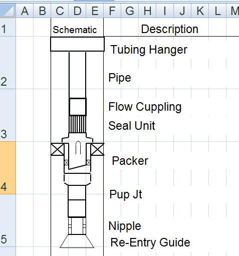
Sample Output:
Constraints and Requirements
Basic components: straight line, rectangle, arc, circle. All shapes are constructed from these pieces or from groupings of these pieces to allow for maximum compatibility.
Components should know how to connect to other components: i.e. line up, packers stretch to the edge of the hole.
There are two required output types to excel. Workover (A more detailed output with larger pieces over multiple pages), Completion (A single sheet overview of the well). These require different drawings for the pieces.
Readable to and from a file for updating.
Components often have common features i.e. seals on packers so [drawings of] sub components should be reusable.
Several pieces of related information that should make up an object. Description, inner diameter, outer diameter, nominal size, notes, component image.
Other non typical objects exist. Such as hole and hole casing.
Other document information: company, well field, well, dates. (Ignored)
The software is expected to be expanded to include wellsite layout and the components as well. This means that later connection will not be limited to vertical connections.
The software may need to export to other file types (i.e. Visio) at a later time.
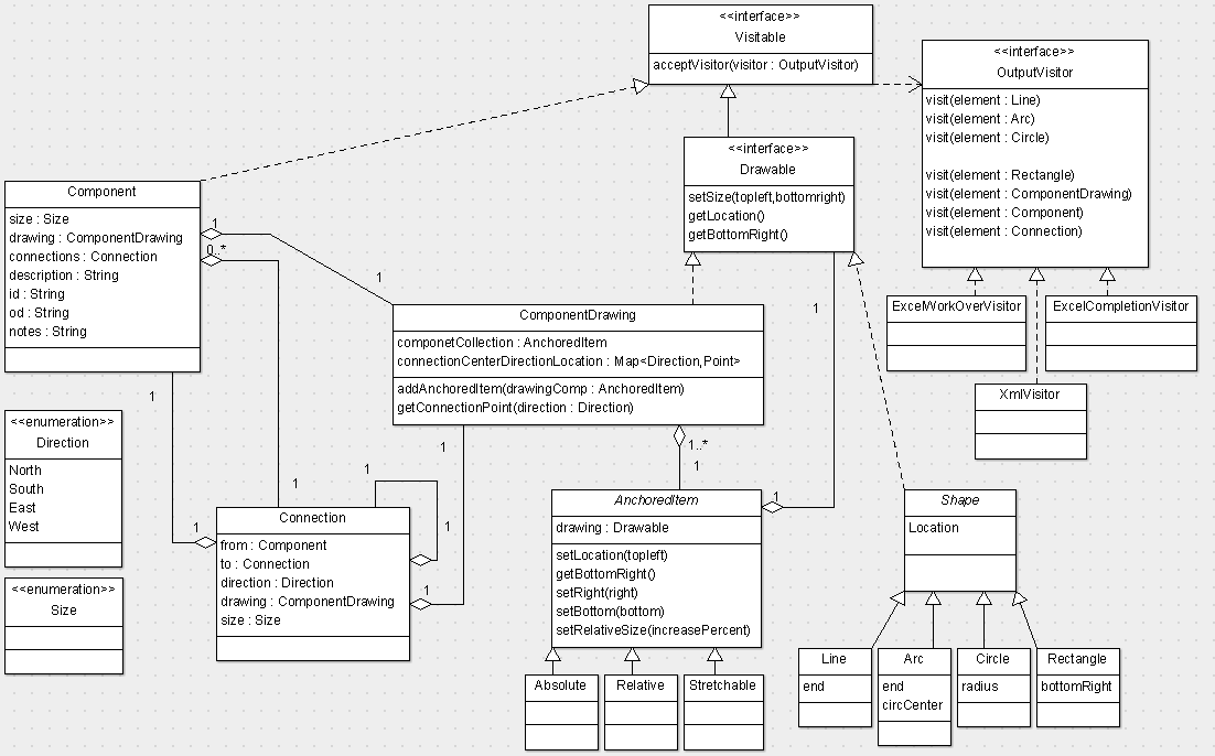
UML:
Explanation
This design project focuses on the representation of the wellsite components in the system and how the information is modeled and output rather than the editor and frontend.
Component: Contains the various details about the component including its connections. It is accessed by the editor and is the starting point for visitors and represents the components in the well.
Size: This enum covers several sizes that are considered standard. The two excel outputs use these to size the component drawings relative to each other. While they are loosely related to I.D. and O.D. these values usually differ. May need to be changed to a full class to include comparison behaviour and for tidier output.
Direction: An enum that informs where a connection is located on a component.
Connection: Seperate the joining behaviour from the components themselves, allows for size checking. The connection also has a ComponentDrawing for when they need to be represented (i.e. drawing the nut of a female connection) not to be confused with the ComponentDrawing for the Component it is related to.
ComponentDrawing: This is a group of basic Shapes and other ComponentDrawings giving a representation of the component. It also contains information on how this drawing aligns with other drawings.
Drawable: Covers the basic information required to locate and align objects.
OutputVisitor: This allows for access to the components represented in the system.
Patterns
Visitor Pattern
The visitor pattern allows for the appropriate information to be used when outputting files. Using this pattern we are able to access the appropriate data and change how the information is processed. For instance excel outputs of completions do not draw connections between components while workovers do. It also allows the appropriate behaviour for converting drawings to excel format and arrange them appropriately while allowing the XmlVisitor to store all information required to reload the file. It also allows extension for other output types such as to Visio at a later time.
Strategy Pattern
The strategy pattern(using the abstract class AnchoredItem rather than an interface) is used to affect resize behaviour. This behaviour can affect how items are anchored in there component allowing them to stretch in the appropriate manner. This allows items such as the seals on packers to be resized appropriately.
Composite Pattern
The ComponentDrawing and Shape relationship are designed around the composite pattern allowing for the drawings to be built up from smaller pieces. This also allows for reuse of drawn components in other areas.

